Ellipse (Eccentricity Method) -- VektorCAD Tutorial
This tutorial shows how to construct an ellipse from its focus, directrix, and eccentricity e using VektorCAD.
Theory
An ellipse is the locus of points P such that PF = e x PD, where F is the focus, PD is the perpendicular distance from P to the directrix line, and 0 < e < 1.
Conventions
- Normal thickness for all construction, projection, and dimension lines
- Thick for the final ellipse curve
carccommand (center+radius arc that cuts a selected entity) to locate precise intersection pointssplineto draw the smooth ellipse
Tutorial Video
Problem Statement
Construct an ellipse when the distance of the focus F from the directrix is equal to 50 mm and eccentricity is e = 2/3.
| Given | Value |
|---|---|
| Distance (Focus to Directrix) | 50 mm |
| Eccentricity (e) | 2/3 |
| Task | Construct ellipse by eccentricity method |
Objective:
| Requirement | Details |
|---|---|
| Commands used | Line, Point, UCS, Carc, Spline, Array, Mirror, Text |
| Construction lines | Normal thickness |
| Final ellipse | Thick thickness |
| Entity Snap | ON throughout |
Step-by-Step
1) Setup
-
Thickness -- set to Normal (Thin / Normal / Thick)

-
Entity Snap ON

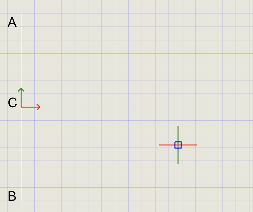
2) Draw the Directrix and Set the UCS Origin
-
Enable Snap: Turn Snap ON so the mouse pointer aligns precisely with the grid points

-
Draw the Directrix: Click Line on the toolbar. Using the mouse cursor, draw a vertical line to represent the directrix
-
Label the Directrix: Click Text on the toolbar and place labels
A(top) andB(bottom) of the vertical line -
Set UCS Origin: Run the UCS command and position the origin directly on the directrix
-
Label the Origin: Use Text to add label
Cnear the UCS origin -
Draw the Axis: With the Line command, draw a line perpendicular to AB to represent the axis
-
Disable Snap: Turn Snap OFF once the origin is set
3) Mark Focus F and Divide CF into 5 Equal Segments
-
Set Point Style: In the Format Panel, change point size to 2 and select the dot ( . ) style
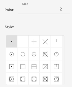
-
Mark the Focus: Click Point on the toolbar. At the prompt, type
50to place focusFat 50 mm from C -
Label the Focus: Use Text to add label
Fnear the focus point -
Change Point Style: Set point size to 4 and switch to vertical bar ( | ) to make division points visually distinct
-
Divide Segment CF:
Step Action a Click Divide from the Point menu b At the prompt, type or click Between c First point: click Con the axisd Second point: click focus Fe Number of segments: type 5and press EnterThis divides
CFinto 5 equal parts (sum of numerator + denominator of eccentricity: 2 + 3 = 5).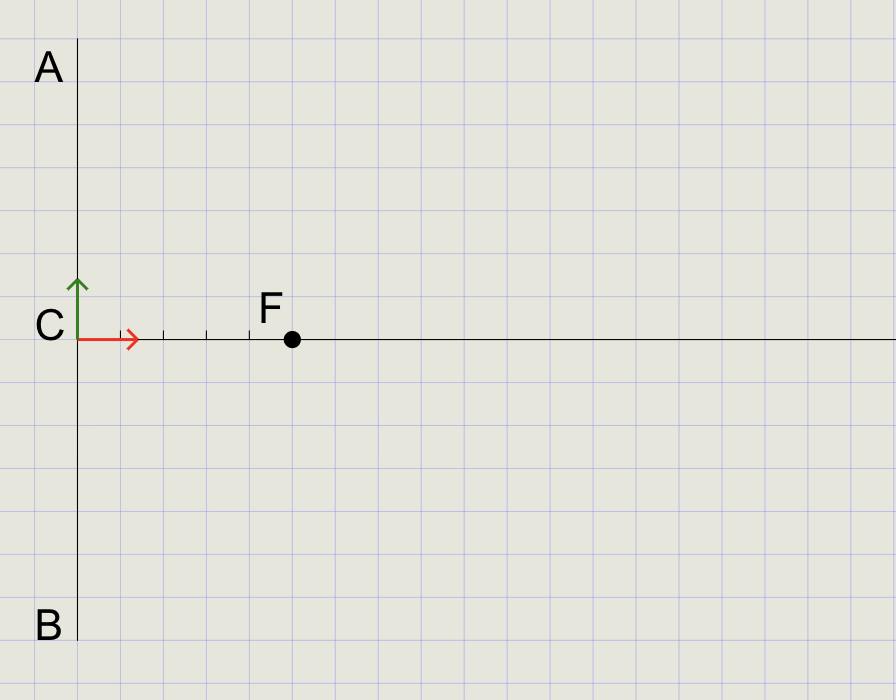
Tip
Use entity snaps like Endpoint and Node for precise selection when clicking points.
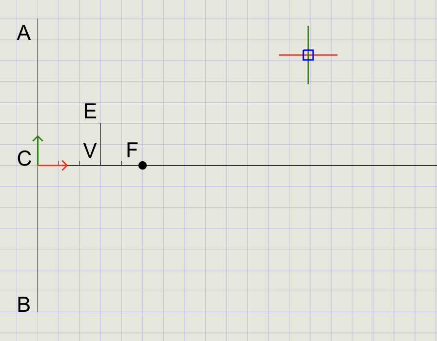
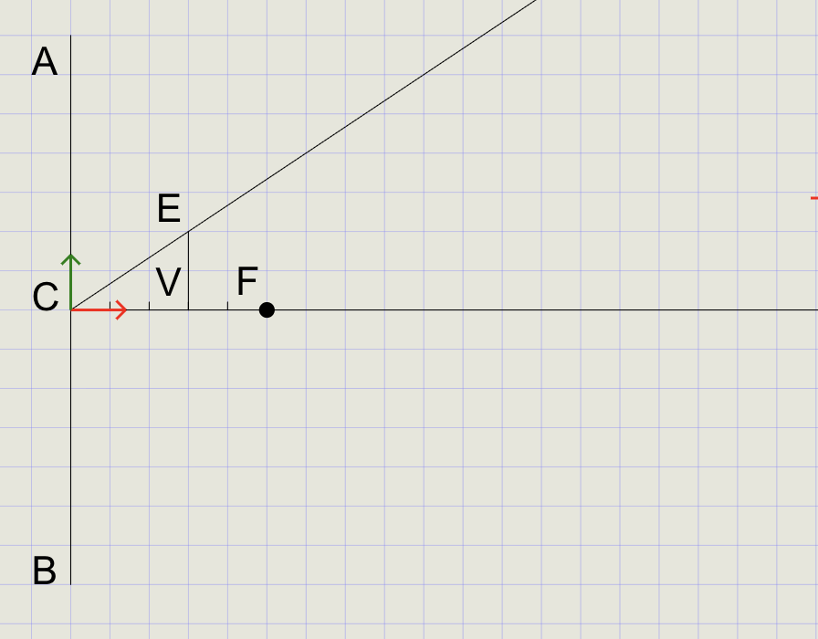
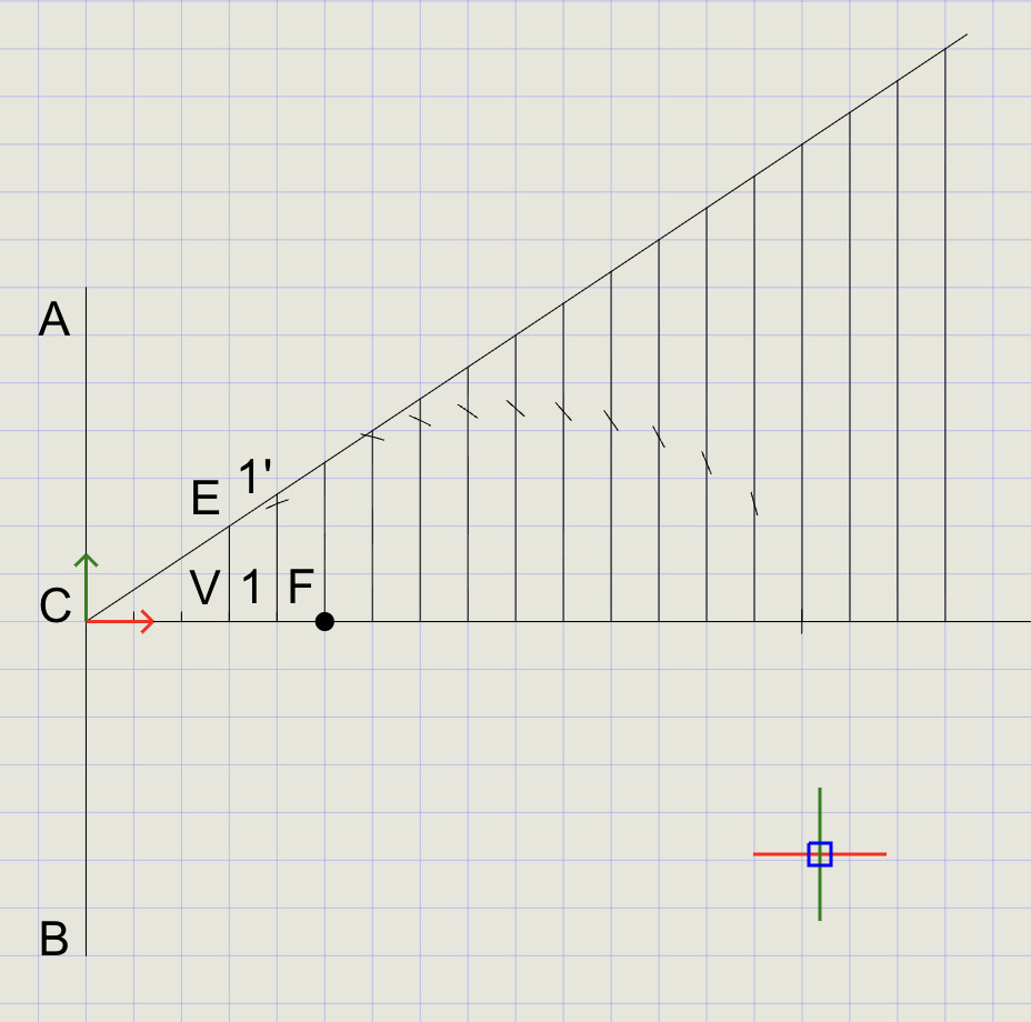
4) Draw VE on the Third Division Point from C
-
Start Line: Click Line and select the third division point from C as the starting point
-
Set Distance Option: At the prompt
Specify next point [Angle/Distance/Undo], choose Distance -
Fix Line Length: Click point
Fto specify the length equal toVF -
Set Angle: At the prompt, type
90to draw the line perpendicular toCF -
Complete Line: Press Enter to finish
-
Label Points: Use Text to label start as
Vand end asE
5) Draw Line CE
- Click Line and draw a line from point
Cto pointE - From the Trim dropdown, select Extend
- Click on line
CEnear pointEto extend it beyondE
6) Draw Line 1-1'
- Turn Ortho ON from the status bar
- Draw a line starting between V and F and extend it so it crosses well over line
CE - Turn Ortho OFF (no longer needed)
- Use Text to label the start as
1and the intersection withCEas1'
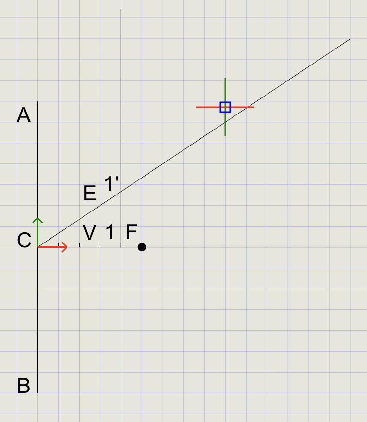
7) Copy Line 1-1' Using ARRAYRECT
- From the Copy dropdown, click Array
- Select line
1-1'and press Enter -
At the prompts:
Prompt Value Number of columns 15Number of rows 1Base point Select point 1Column spacing 10(mm apart)Row spacing 1
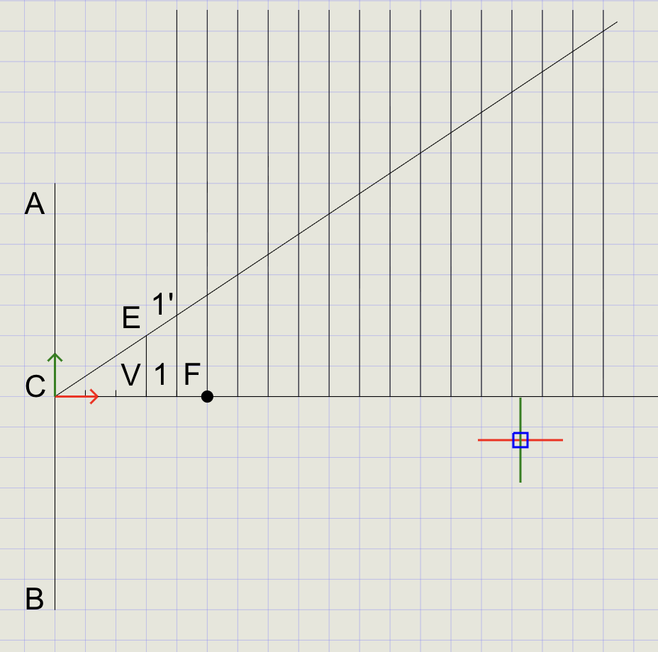
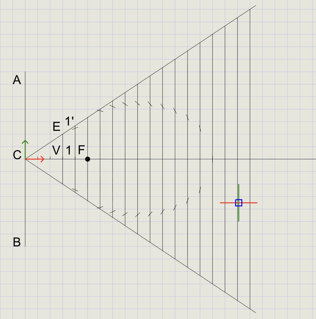
8) Trim the Extended Lines
- Click Trim on the toolbar
- At the prompt, select all portions of the vertical lines above line CE
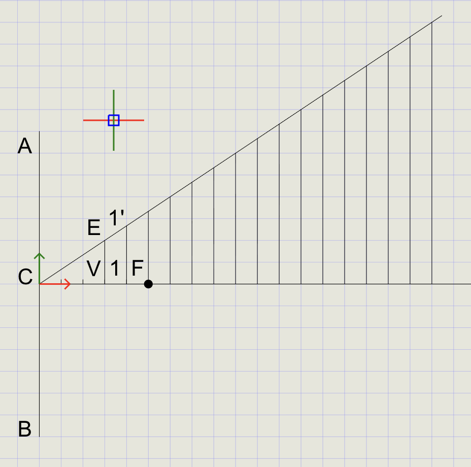
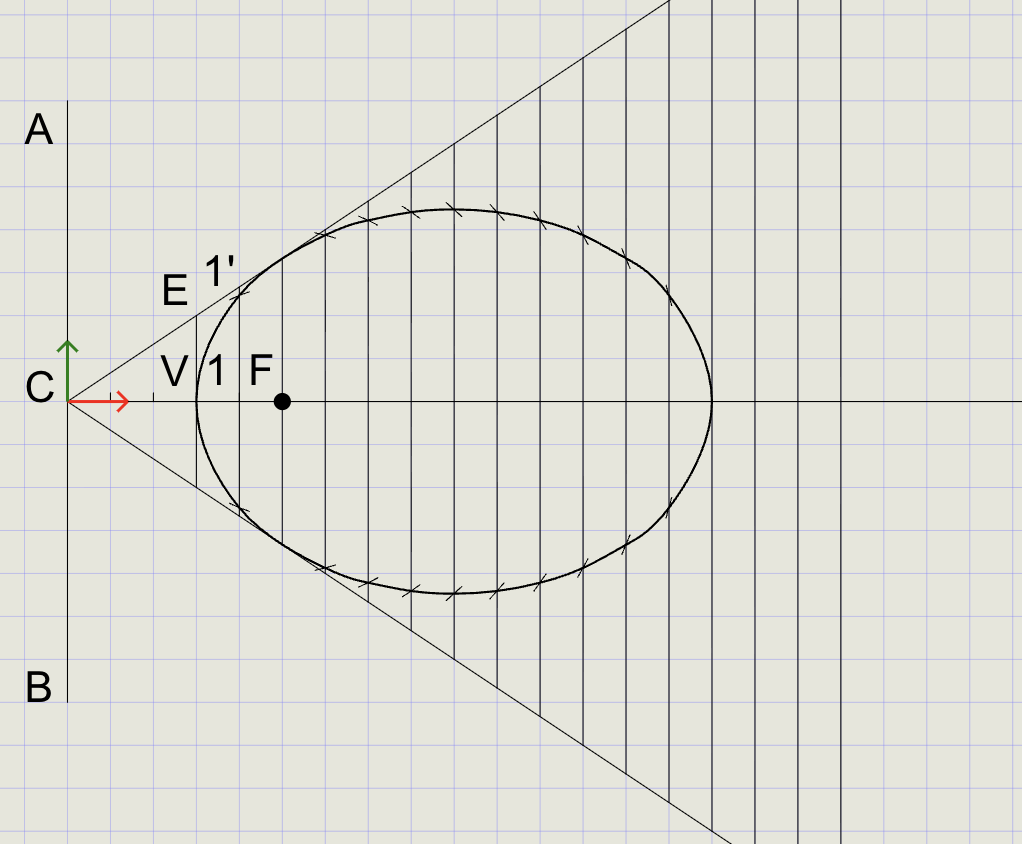
9) Draw Arcs to Cut the Lines
- From the Arc dropdown, click Cutting Arc
-
At the prompts:
Prompt Action Specify radius Select points 1and1'Specify center point Select point FSpecify curve to cut Select line 1-1' -
An arc is created that cuts line
1-1' - Press Enter to repeat Cutting Arc
- Repeat the process for all other vertical lines
10) Mirror Lines and Arcs
- From the Copy dropdown, click Mirror
- Select all vertical lines, arcs, and line
CE, then press Enter -
At the mirror prompts:
Prompt Action Mirror reference start Click point CMirror reference end Click point F
11) Draw the Final Spline
- In the Format Panel, switch to Thick line thickness
- Click Spline on the toolbar
- Starting from point
V, pick all line/arc intersection points in clockwise order - To close the spline, click Close (do not re-select
V)
Tip
Picking points in consistent clockwise or counter-clockwise order ensures a smooth spline without crossings.
12) Draw Tangent and Normal
Step A -- Pick a point on the ellipse:
-
Click the Point menu, then right-click and select Nearest
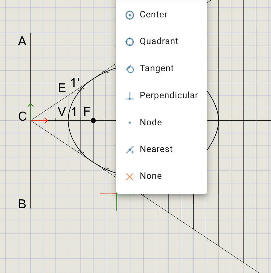
-
Hover near the ellipse and pick a point. Mark it as
Sand draw lineFS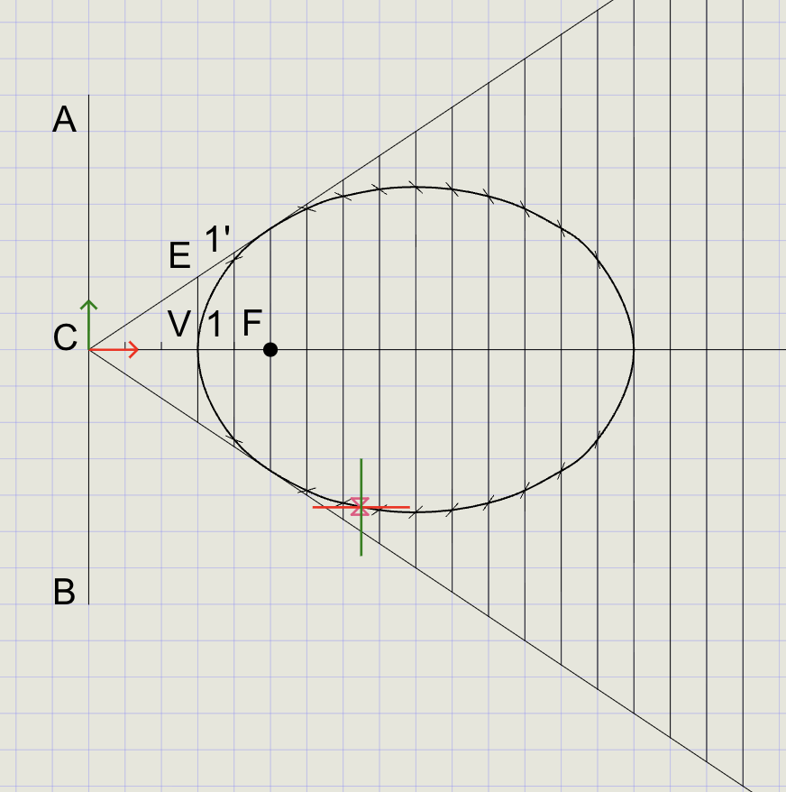
Step B -- Construct auxiliary line:
- From the Line dropdown, choose Perpendicular
- Select line
FS - Start at
Fand extend it to cross the directrixAB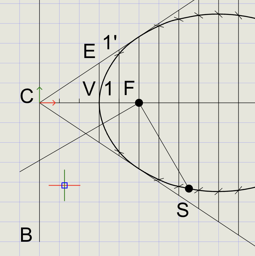
Step C -- Draw the tangent:
- From the Line menu, pick the intersection point on directrix
AB - Choose Angle and select point
Sfor direction - Pick a point beyond
Sto complete the tangent, then press Enter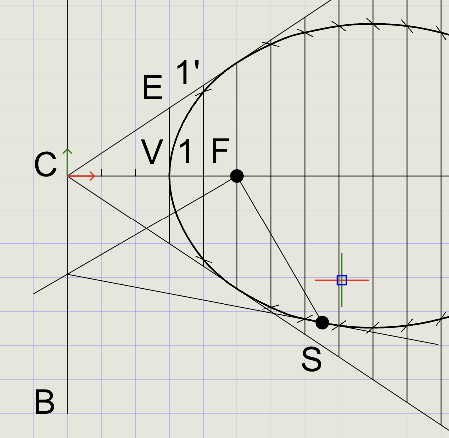
Step D -- Draw the normal:
- From the Line dropdown, choose Perpendicular
- Select the tangent line
- Start at
Sand pick a point outside the ellipse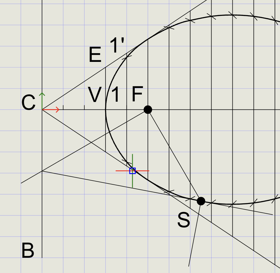
Result Checklist
| Item | Status |
|---|---|
Directrix d and Focus F labeled |
|
Axis drawn perpendicular to directrix through F |
|
Offset lines parallel to directrix at distances d |
|
carc used with center = F and radius = e x d to cut offset lines |
|
| Closed spline passes smoothly through intersection points | |
| Final ellipse in Thick; construction in Normal | |
| Labels and sample dimensions added |
Variations (Practice)
| Variation | What to try |
|---|---|
| Different eccentricity | Rebuild with e = 1/2 or e = 3/4 |
| Different focus distance | Move focus closer/farther from the directrix |
| Quadrant + Mirror | Generate only one quadrant and mirror across principal axes |
| Compare methods | Draw from major/minor axes (conjugate-rectangle method) and compare |
Commands Recap
| Command | Purpose |
|---|---|
line |
Directrix, axis, parallels (offset lines) |
point |
Mark focus F, foot N, and division points |
ucs |
Place/align axes to simplify perpendicular offsets |
arrayrect |
Copy array of lines with equal spacing |
trim |
Trim extra line portions |
carc |
Center + radius arc to cut offset lines and reveal intersection points |
mirror |
Mirror entities from one side to the other |
spline |
Fit smooth closed curve through points (the ellipse) |
text |
Labels and notes |
| Format | Normal for construction, Thick for final curve |
Export and share
You've drawn an ellipse by the eccentricity method using carc to locate accurate points and spline to produce a clean curve. Export to PDF to verify and share your work.