Orthographic Projection Drawing -- VektorCAD Tutorial
This tutorial walks you through creating orthographic views (Front, Top, and Right-Side) of a simple mechanical part in first-angle projection using VektorCAD.
Line weight conventions
| Thickness | Used for |
|---|---|
| Thick | Final visible outlines |
| Thin | Projection lines and construction |
| Normal | Dimensions |
| Hidden linetype | Invisible (hidden) edges |
First-angle projection
- Top View is placed below the front view
- Front View is above XY
- Right-Side View is placed to the left of the front view
(Switch positions if your standard requires third-angle projection.)
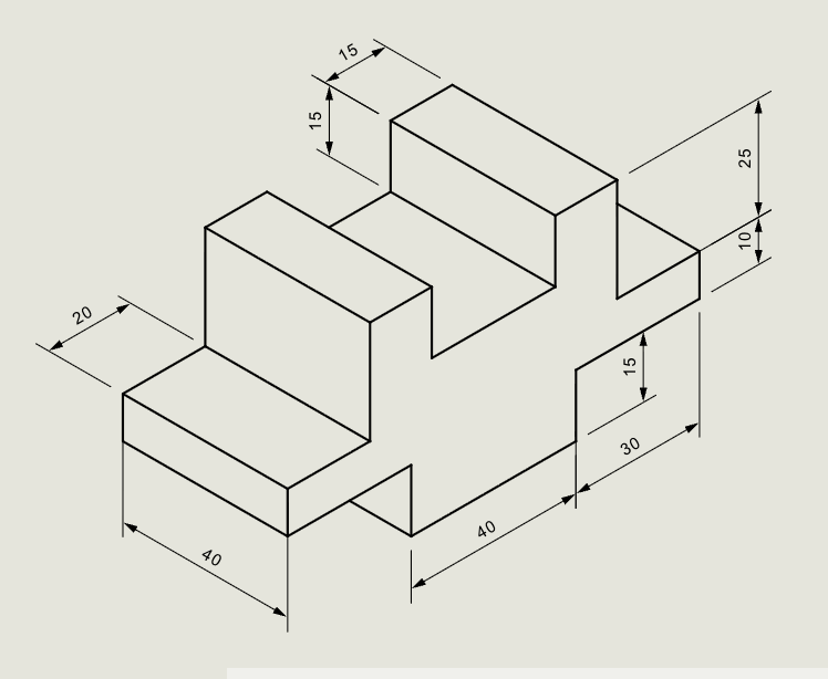
Problem Statement
The pictorial view of a block is given. Using first-angle projection, draw its front view, side view, and top view.
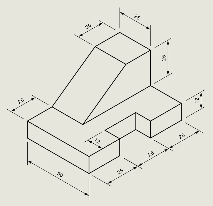
| Given | Value |
|---|---|
| Object | Isometric view of a block |
| Projection method | First-angle |
| Views required | Front view, Top view, Right-side view |
Objective:
| Requirement | Details |
|---|---|
| Commands used | Line, Rect, Ray, Offset, Trim, DimLin, Text |
| Visible edges | Thick thickness |
| Projection lines | Thin thickness |
| Dimensions | Normal thickness |
| Hidden edges | Hidden linetype, Normal thickness |
| Snaps | Entity Snap ON throughout |
Step-by-Step
1) Setup
| Setting | Action |
|---|---|
| Thick | For visible outlines |
| Thin | For projectors/construction lines |
| Normal | For dimensions |
| Snap ON | Align with grid |
| Entity Snap ON | Endpoint, Midpoint, Center |
| Ortho ON | For horizontal/vertical lines |
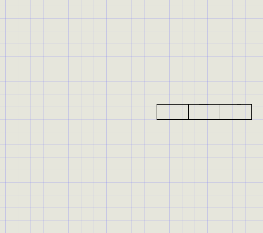
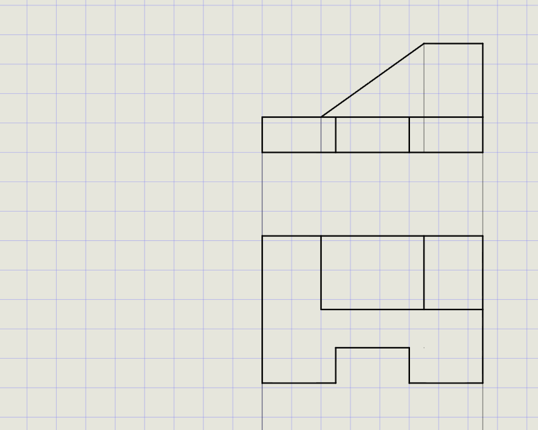
2) Front View (Visible Outlines in Thick)
Draw the base block:
- Switch thickness to Thick
-
From the Rect menu, draw a rectangle:
- First point: center of sheet
- Second point:
@75,12 - This forms the base block
-
Create slot edges using Offset:
Offset from Distance Direction Left edge 25 Towards right Right edge 25 Towards left
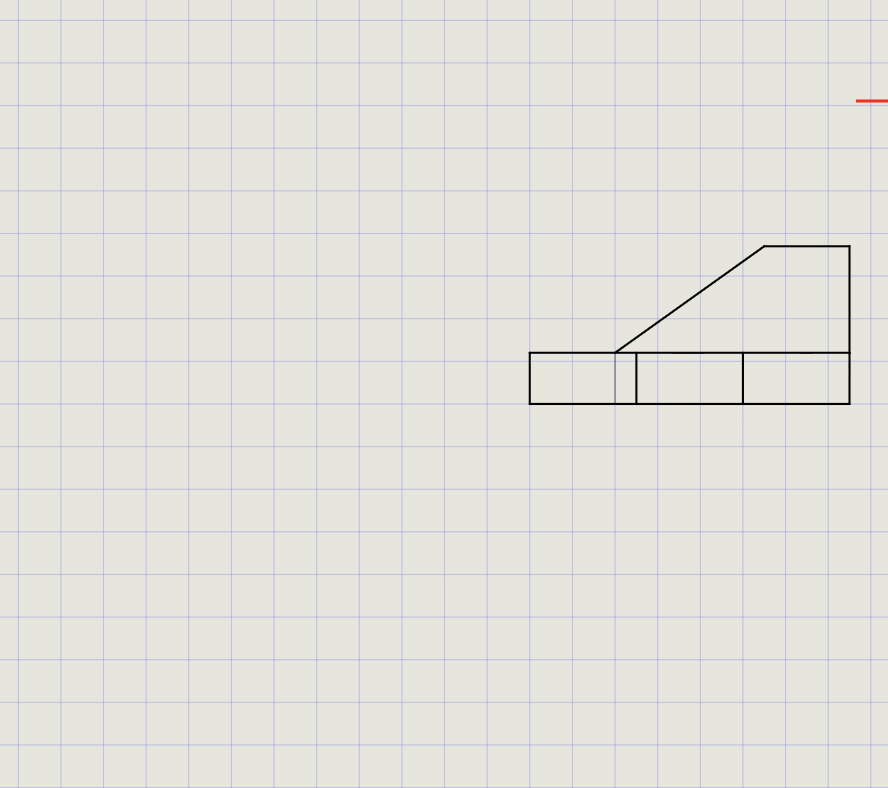
Add the top projection:
- From the top-right corner, draw vertical line
@0,25 - From the endpoint, draw horizontal line
@-20,0 -
Press Enter to finish
-
Switch thickness to Thin
- Offset left side of rectangle by
20towards right (reference line) - Switch back to Thick
- Draw connecting line from the top of the vertical extension to the offset line
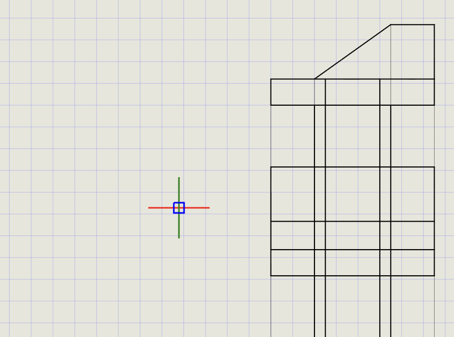
3) Project to Top View
- Switch thickness to Thin
- From Line > Ray, enter angle =
-90(downward) - Project rays from all corners of the front view
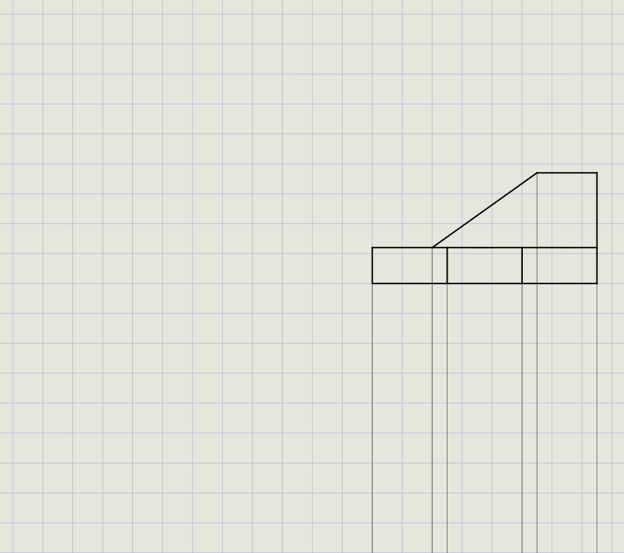
- Switch thickness to Thick
-
From Rect, draw boundary rectangle:
- Snap to leftmost projector below front view
- Enter
@75,-50for size
-
Use Offset to mark internal edges:
Offset distance Purpose 12 Depth of base step 25 Slot boundary 20 Top feature width
- Use Trim to remove unwanted lines and finalize the top view
4) Transfer to Right-Side View
- From the Top View, repeat the projection process:
- Draw rays horizontally from top view corners
- Construct the side view rectangle and internal features using offsets
- Place the Right-Side View to the left of the Front View (first-angle convention)
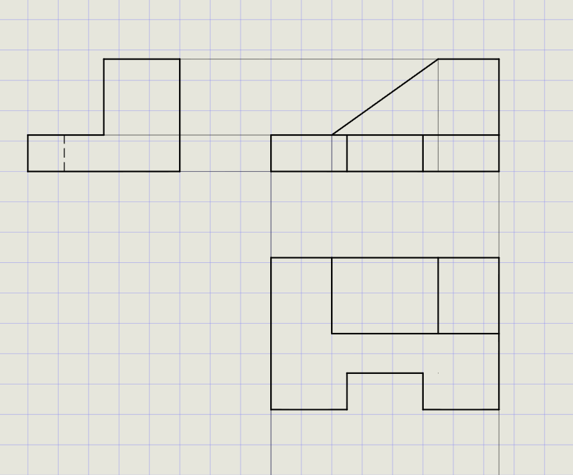
Tip
Use the same offset distances as the front view height features to maintain consistency between views.
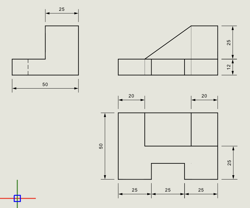
5) Dimensions and Labels
- Switch thickness to Normal
-
Use Dimension tools:
Dimension type Use for DimLin Linear sizes (length, width, height) DimAlign Slanted features -
Add overall length, width, and height dimensions
- Label views using Text (Front View, Top View, Side View)
Result Checklist
| Item | Status |
|---|---|
| Front View: outer profile in Thick | |
| Top View: outer profile in Thick, projected from front view | |
| Right-Side View: placed to the left (first-angle), profile in Thick | |
| Projection lines in Thin, clean and not overlapping views | |
| Hidden edges shown with Hidden linetype (Normal thickness) | |
| Dimensions in Normal thickness, readable and placed correctly |
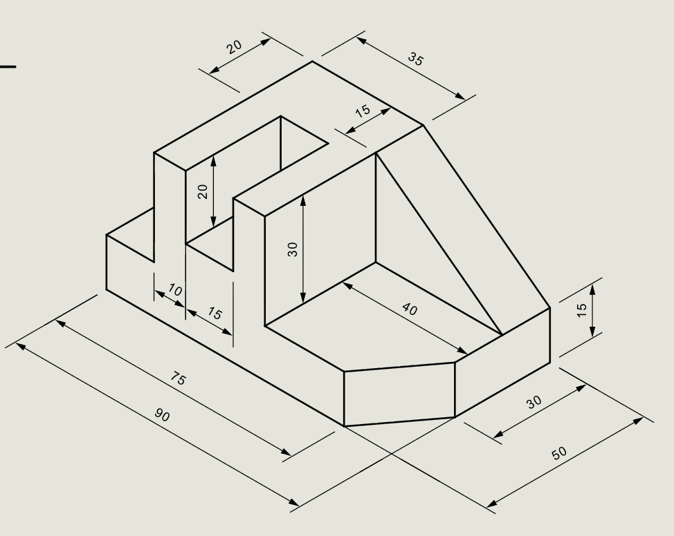
Variations (Practice)
Practice orthographic projection with these additional blocks:
| Variation | What to try |
|---|---|
| Third-angle projection | Top view above, side view to the right |
| More complex geometry | Add holes, chamfers, or fillets to the block |
| Hidden edges | Use Hidden linetype for edges not visible from the viewing direction |
| Centerlines | Add center linetype for holes and cylindrical features |
Commands Recap
| Command | Purpose |
|---|---|
line |
Projectors, miter lines, and outlines |
rect |
Fast view boundary rectangles |
ray |
Projection rays at specific angles |
offset |
Mark internal edges at known distances |
trim |
Remove unwanted line segments |
dimlin |
Linear dimensions |
dimalign |
Aligned dimensions for slanted features |
text |
View labels and annotations |
| Format Panel | Set Thickness (Thin/Normal/Thick) and Linetype (Continuous/Hidden/Center) |
| Status Bar | Entity Snap, Ortho, Snap toggles |
Complete
You've completed an orthographic projection drawing using first-angle layout, proper line weights, hidden edges, and dimensions. Export to PDF to verify scale and line weights in print preview.