Projection of a Solid -- VektorCAD Tutorial
This exercise shows how to construct the projections of a solid (hexagonal prism) using VektorCAD. You will begin with the base in true shape, project to the other view, then impose the required inclination by rotating with arcs and projectors.
What you'll learn
- Constructing the true-shape base using the Polygon command
- Projecting from front view to top view (and vice versa)
- Rotating views to impose axis inclination
- Distinguishing visible and hidden edges in the final projection
Problem Statement
Draw the projections of a regular hexagonal prism of base side 25 mm and axis length 60 mm. The prism rests with one of its rectangular faces on HP such that its axis is inclined at 45 degrees to VP.
| Given | Value |
|---|---|
| Solid | Regular hexagonal prism |
| Base side | 25 mm |
| Axis length | 60 mm |
| Resting position | One rectangular face on HP |
| Axis inclination to VP | 45 degrees |
Objective:
| Requirement | Details |
|---|---|
| Commands used | XYLine, UCS, Polygon, Line, Arc, Point, DimLin, DimAlign, Text |
| Construction lines | Normal thickness |
| Final visible edges | Thick thickness |
| Entity Snap | ON throughout |
Step-by-Step
1) Prepare Drafting Settings
-
Set Line Thickness: Select Normal (Thin / Normal / Thick) -- use for XY, projectors, and dimensions
-
Enable Snaps: Turn Snap ON and Entity Snap ON (recommended: Endpoint, Midpoint, Perpendicular)
-
(Optional) Toggle Ortho ON for strict horizontals and verticals
2) Draw the XY Reference Line
- Run
XYLINE - Draw a horizontal line approximately 180 mm across the sheet
- This is your XY reference line
3) Construct the True Shape of Hexagon in Front View
Since the prism rests with a rectangular face on HP, start by constructing the hexagonal base in the front view.
- From the Rect/Polygon dropdown, click Polygon
-
At the prompts:
Prompt Action Number of sides Enter 6Method Choose Edge First endpoint Pick a point on XY line Second endpoint Enter @25,0(25 mm horizontal edge) -
Label vertices a'(1'), b'(2'), c'(3'), d'(4'), e'(5'), f'(6') using Text
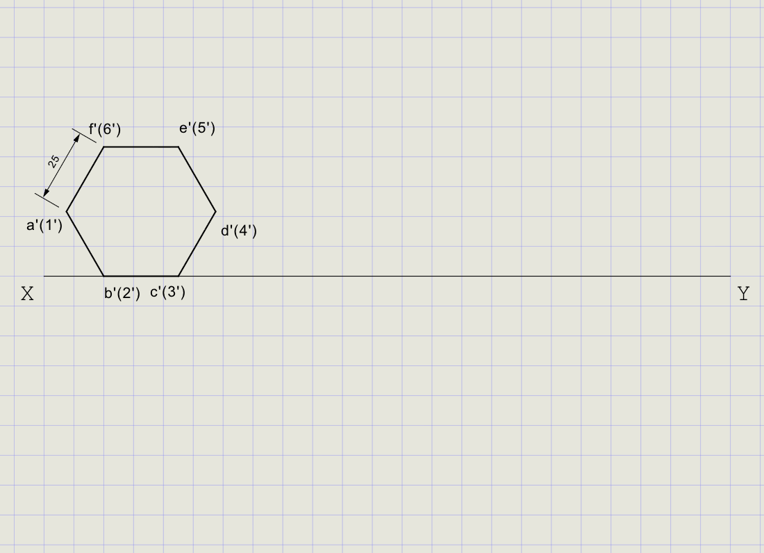
Note
The Edge method places one side of the hexagon directly on XY, representing the face resting on HP.
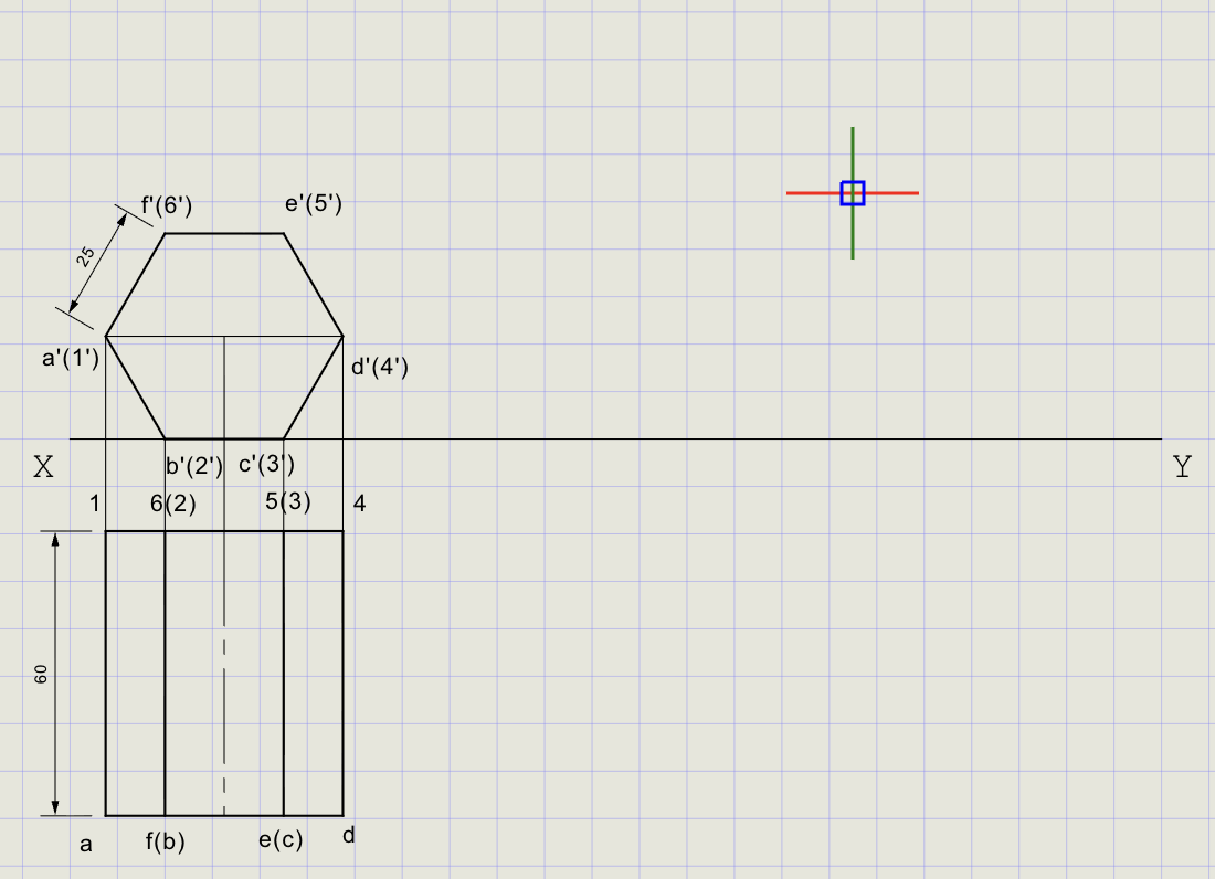
4) Project Initial Top View
- From each hexagon vertex (a'-f'), draw vertical projectors downward below XY
- On each projector below XY, mark the corresponding top view points
- Draw vertical edges of length 60 mm to represent the prism's axis
-
Complete the prism outline in front view
View What it shows Front view Hexagon (true shape of base) + rectangular axis outline Top view Rectangle (60 mm long) with projections of all edges
5) Incline Axis at 45 degrees to VP (Rotate in Top View)
- In the top view, identify the prism axis (center-to-center line)
- Draw a new axis line at 45 degrees to XY through one corner (e.g., point a)
-
Use Cutting Arc to transfer vertex distances from the original top view to the inclined axis:
Action Details Center Base corner (a) Radius Distance from a to each vertex in original top view Cut The inclined axis or parallel lines -
Redraw the hexagonal top view in the tilted orientation
- Project vertical edges to represent the prism in the tilted top view
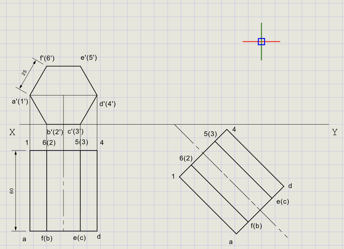
Tip
The cutting arc ensures exact distances are preserved during rotation -- the prism dimensions don't change, only its orientation.
6) Obtain Final Front View
- From tilted top view vertices (a-f), draw vertical projectors upward to XY
- From original front view edges, draw horizontals across
- Intersections give the final front view vertices a'-f'
-
Join points to complete the prism outline
-
Apply line weights:
Edge type Thickness Visible edges Thick (solid lines) Hidden edges Normal (dashed lines)
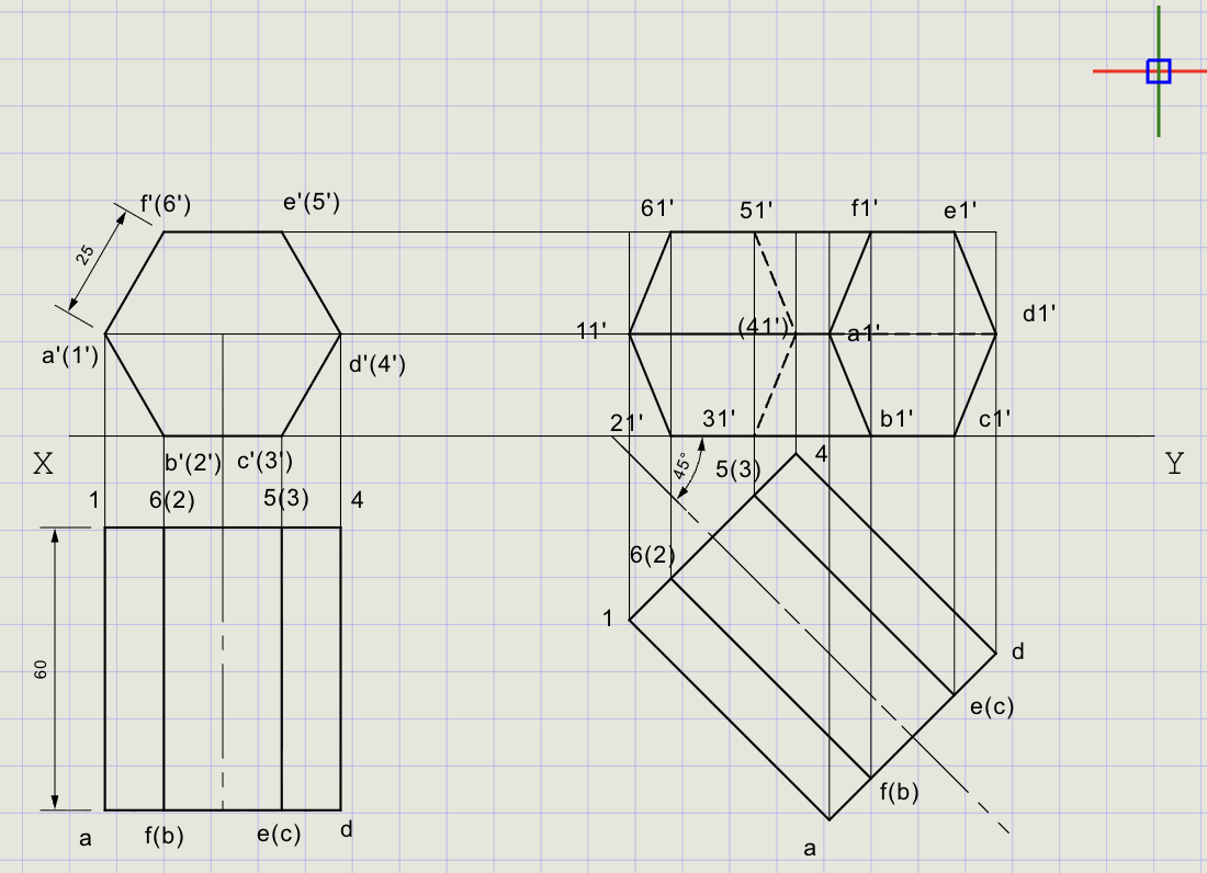
Note
Visible edges are those facing the observer. Hidden edges (behind the solid) are drawn with dashed lines to distinguish them.
Final Result
| View | Description |
|---|---|
| Top View | Inclined hexagonal prism with axis at 45 degrees to VP |
| Front View | Projected prism resting on HP, axis inclined to VP |
| Edge treatment | Visible = Thick solid; Hidden = Normal dashed |
Result Checklist
| Item | Status |
|---|---|
| XY drawn (Normal) and labeled | |
| Entity Snap ON; UCS positioned conveniently | |
| Hexagonal base (true shape) constructed in front view | |
| Initial top view projected with axis length 60 mm | |
| Axis rotated to 45 degrees to VP using cutting arcs | |
| Final front view obtained by intersection of projectors and horizontals | |
| Visible edges in Thick; hidden edges in Normal dashed | |
| Dimensions and labels placed |
Variations (Practice)
| Variation | What to try |
|---|---|
| Square pyramid | Base 30 mm, axis 60 mm, resting on HP; use polygon with 4 sides, apex at axis end |
| Pentagonal prism | Side 20 mm, axis 50 mm; similar steps with 5-sided base |
| Cylinder | Use circle for base, line for generators; tilting steps are analogous |
| Cone | Base as circle, apex by axis length; rotate using arcs from base center |
| Different angle | Try axis at 30 or 60 degrees to VP |
Commands Recap
| Command | Purpose |
|---|---|
xyline |
Draw XY reference line (Normal) |
ucs |
Reposition origin for convenient numeric input |
polygon |
Base construction (hexagon, side = 25 mm, Edge method) |
line |
Projectors, reference rays, axis, envelope edges |
carc |
Rotate/transfer views to impose inclination |
point |
Mark key points (axis endpoints, intersections) |
dimlin / dimalign |
Linear and aligned dimensions |
text |
Labels, notes, angle callouts |
| Format | Normal for construction; Thick for final visible outlines |
Complete
You've completed the projection of a solid by combining true-shape construction with axis rotation, clearly separating final visible edges (Thick) from construction (Normal). Export to PDF to verify and share.