Isometric Drawing -- VektorCAD Tutorial
This tutorial shows how to create a clean isometric pictorial in VektorCAD using the built-in isometric mode. You will draw each face on the correct ISO plane, add isometric circles for holes, and dimension the final drawing.
Line weight conventions
| Thickness | Used for |
|---|---|
| Thick | Final visible edges |
| Normal | Construction lines, dimensions, hidden edges |
| Hidden linetype | Invisible edges behind the solid |
| Center linetype | Centerlines for holes |
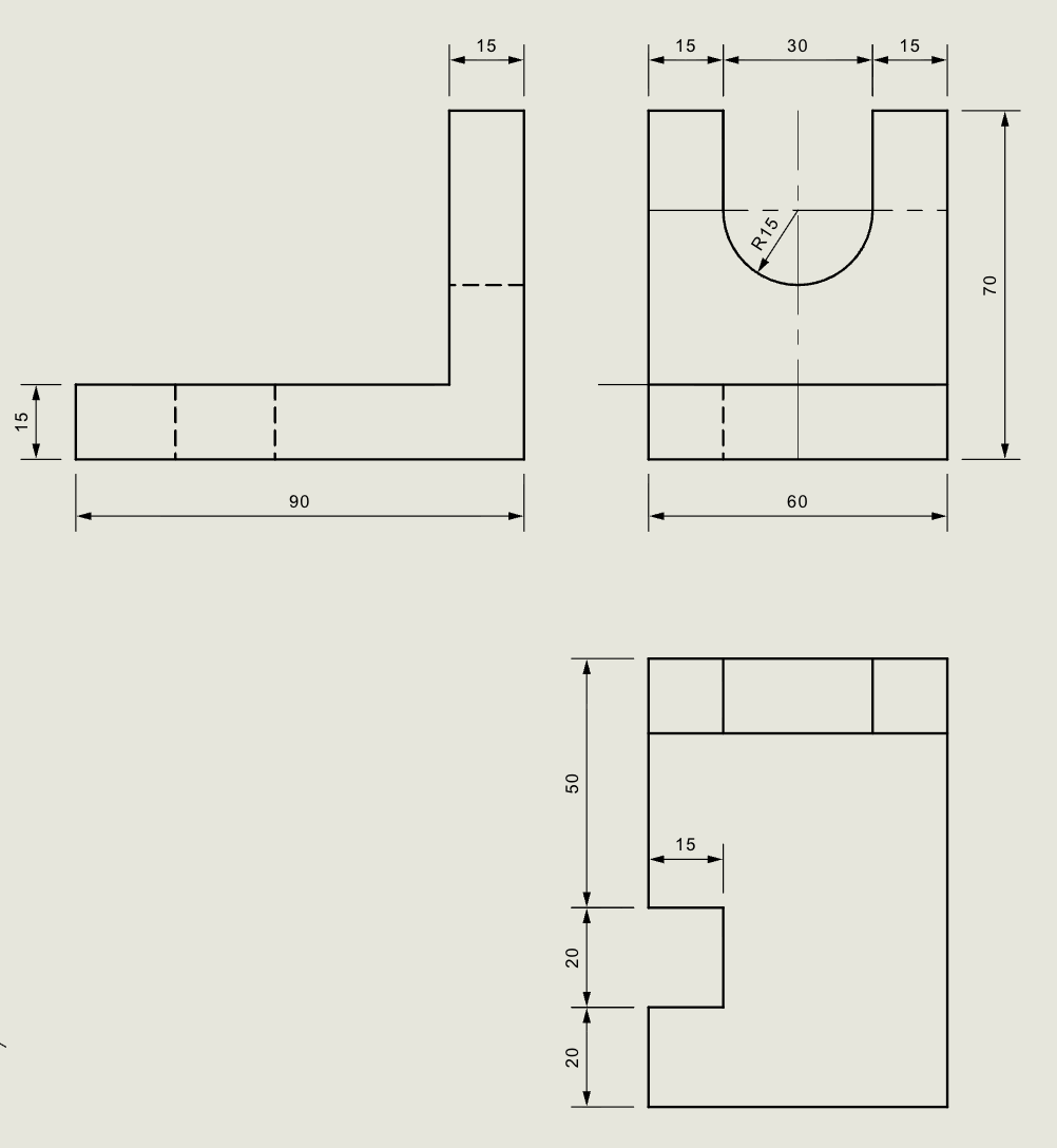
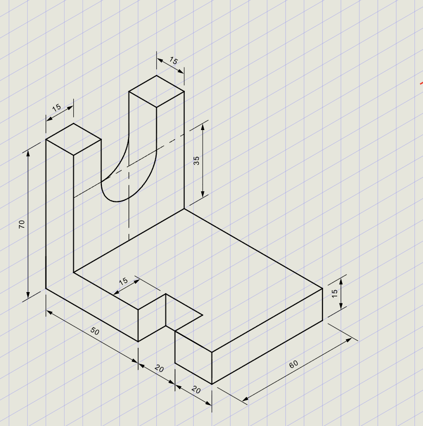
Problem Statement
Draw the isometric projection for the block shown in the orthographic views below.
Objective:
| Requirement | Details |
|---|---|
| Commands used | Line, Ellipse (IsoCircle), Copy, Trim, DimAlign, Oblique, Text |
| Visible edges | Thick thickness |
| Construction / dimensions | Normal thickness |
| Isometric mode | ON (ISO Left, ISO Top, ISO Right) |
| Entity Snap | ON throughout |
Isometric Basics
| Concept | Description |
|---|---|
| Isometric axes | Three axes at 120 degrees apart (30-degree left, 30-degree right, vertical) |
| ISO Left plane | Left face of the object (angles: 90 and 150 degrees) |
| ISO Top plane | Top face of the object (angles: 30 and 150 degrees) |
| ISO Right plane | Right face of the object (angles: 90 and 30 degrees) |
| Isometric angles | Use @length<angle where angle is 0, 90, 180, or 270 (mapped to ISO axes) |
| IsoCircle | Draws an ellipse that represents a circle on the active ISO plane |
Step-by-Step
1) Setup
- Thickness: Set to Normal (Thin / Normal / Thick)
- Entity Snap ON: Endpoint, Midpoint, Center recommended
- Isometric ON: Turn Isometric mode ON in the status bar and select ISO Left to begin
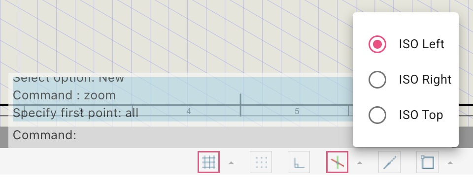
Tip
When Isometric mode is ON, the cursor crosshairs rotate to match the active ISO plane. Switch planes as you move between faces.
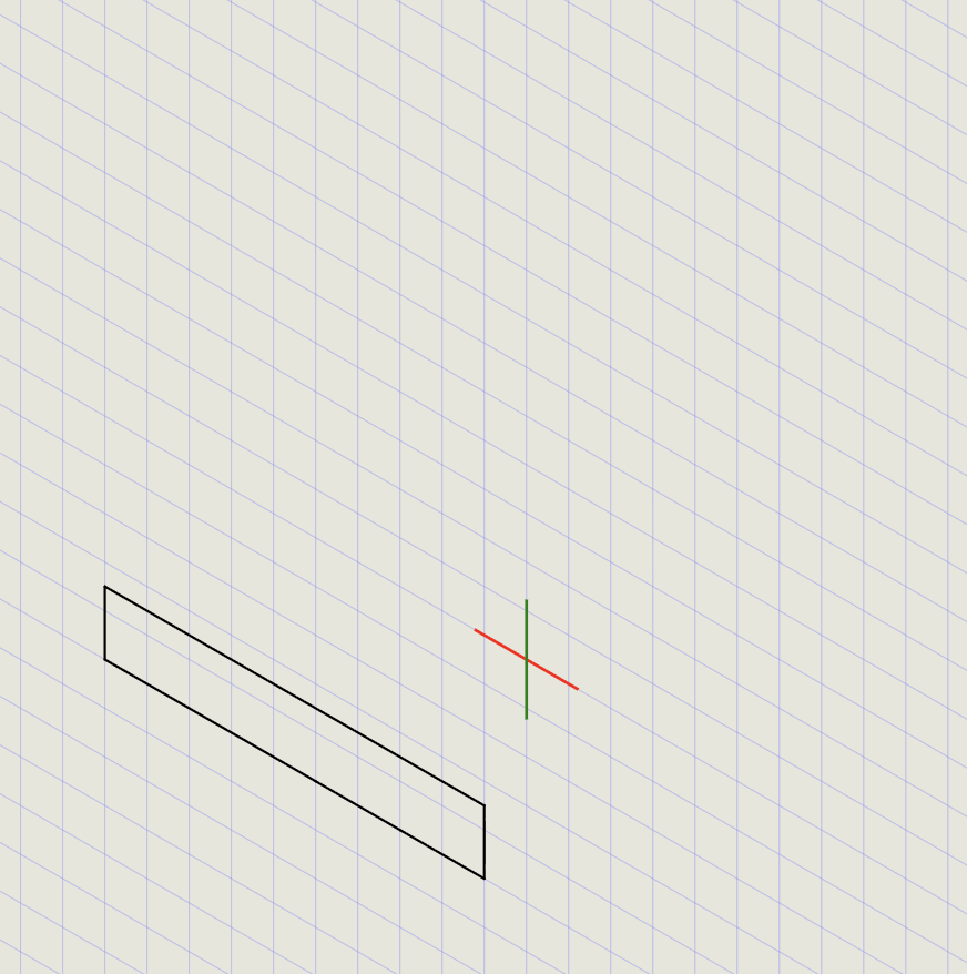
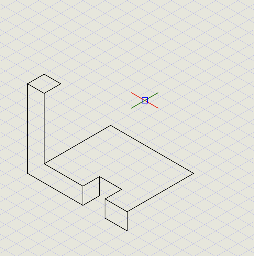
2) Draw the Left Face
- Start the Line command at the bottom corner
-
Enter the following polar coordinates in sequence:
Input Direction @50<0Along bottom-left axis @20<0Continue along bottom @20<0Continue along bottom @15<90Vertical up @90<180Along top-left axis cClose the shape
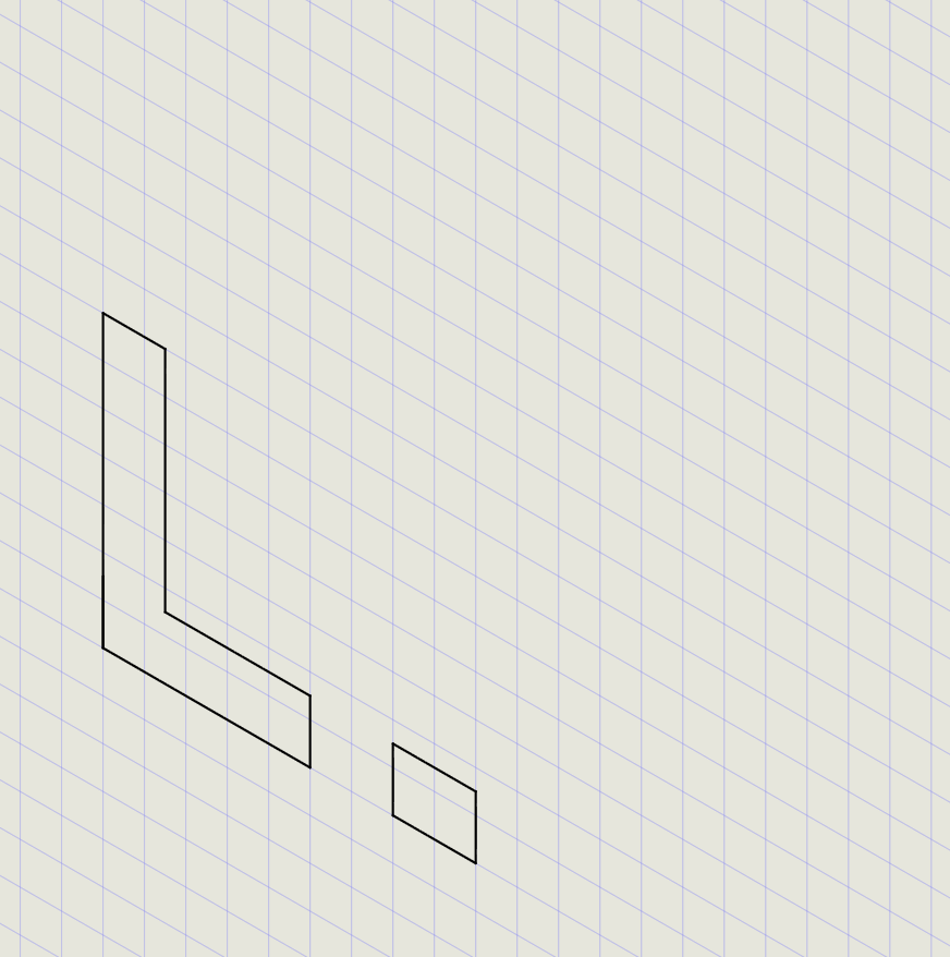
- Draw a Line using end snap at the 50 mm mark -- draw a vertical line to cut the top edge
- Repeat at the 70 mm mark
- Start a new Line at the bottom corner
- Enter
@70<90,@15<0,@70<270and press Enter to create the L-shape left face - Use Trim to remove intersection lines
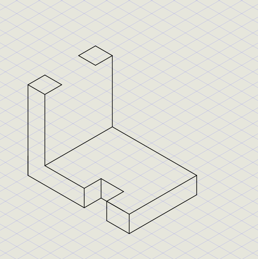
3) Draw the Top Face
- Change ISO plane to ISO Top in the status bar
- Turn Snap OFF and keep Entity Snap ON
- Start Line and pick the endpoint at the L-shape inner corner
- Enter
@60<90,@75<0and pick the end of the L-shape to draw the top face - Draw the other top face edges as shown:
- Copy lines to complete all top faces
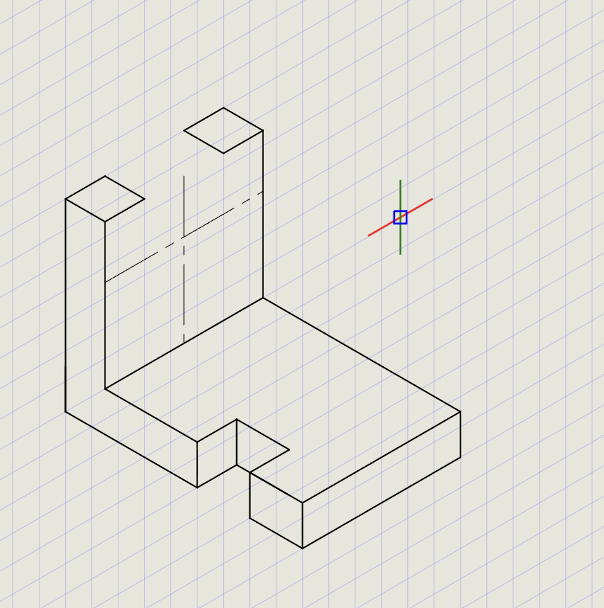
4) Draw the Right Side
- Change ISO plane to ISO Right in the status bar
-
Copy the line at the inner corner of the L-shape:
Action Details Base point Corner point Second point @35<90(vertical offset) -
Copy the vertical line (inner edge of L):
Action Details Base point Corner point Second point @30<0(horizontal offset) -
Select both new lines, change thickness to Normal and set Chain stroke
Draw isometric circles (holes):
- From the Circle dropdown, click Ellipse
- Click IsoCircle option to draw an isometric circle
- Pick the intersection point of the construction lines
- Enter
15for the radius - Use Trim to remove the top semicircle
- Draw lines connecting the ends of the semicircle
- Copy the semicircles and lines, then Trim extensions
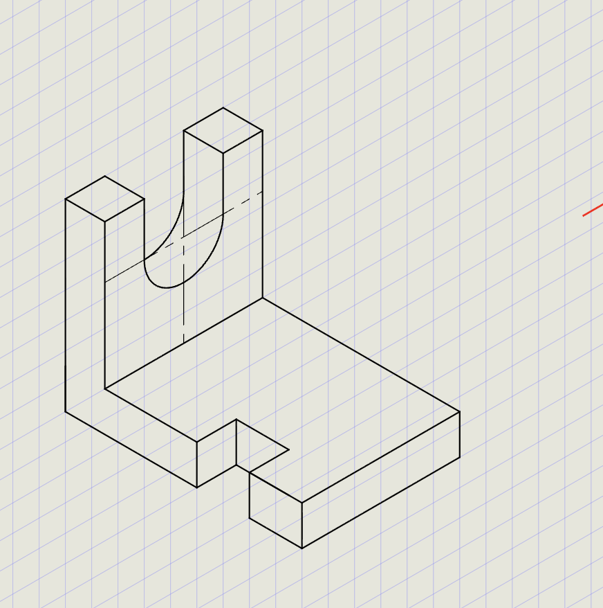
Note
IsoCircle automatically draws the correct ellipse for the active ISO plane. Make sure you're on ISO Right when drawing circles on the right face.
5) Add Dimensions
- Switch thickness to Normal
- From the Dimension submenu, click Aligned
- Draw the necessary dimensions on each face
-
Use Oblique command from the Dimension submenu to align dimensions to isometric views:
Oblique angle Aligns to 30Right-side isometric axis -30Left-side isometric axis -
Select each dimension and enter the appropriate oblique angle
Tip
The Oblique command rotates the dimension extension lines so they follow the isometric axes, making dimensions readable and correctly oriented.
Result Checklist
| Item | Status |
|---|---|
| Isometric mode ON with correct ISO plane for each face | |
| Left face drawn with correct L-shape profile | |
| Top face completed with all edges | |
| Right side with isometric circles for holes | |
| Visible edges in Thick; construction in Normal | |
| Dimensions aligned to isometric axes using Oblique | |
| Hidden edges shown with Hidden linetype (if applicable) |
Commands Recap
| Command | Purpose |
|---|---|
line |
Isometric edges and axes (@len<angle) |
ellipse (IsoCircle) |
Isometric circles for holes/bosses |
copy |
Duplicate edges and features |
trim |
Remove unwanted line segments |
dimalign |
Aligned dimensions |
oblique |
Rotate dimension extensions to match ISO axes (30 or -30) |
text |
Labels and annotations |
| Format Panel | Set Thickness (Normal/Thick) and Linetype (Continuous/Hidden/Center) |
| Status Bar | Entity Snap, Isometric mode (ISO Left/Top/Right) |
Complete
You've completed an isometric drawing with correct axes, line weights, isometric circles, and readable dimensions. Export to PDF to verify line weights and scale in print preview.