Projection of a Line -- VektorCAD Tutorial
This exercise guides you through drawing the projections of a straight line inclined to both reference planes. You will construct the XY reference line, locate endpoint projections, build auxiliary views for each inclination, and rotate to satisfy both given angles.
What you'll learn
- Drawing XY line and locating endpoint projections
- Constructing auxiliary front view (inclination to HP)
- Constructing auxiliary top view (inclination to VP)
- Using arc rotation to obtain final views
- Dimensioning true length and distances from XY
Problem Statement
Draw the projections of a line AB of true length 80 mm.
Endpoint A is 20 mm above HP and 25 mm in front of VP. The line is inclined at theta = 35 degrees to HP and phi = 45 degrees to VP.
| Given | Value |
|---|---|
| True length (AB) | 80 mm |
| Point A above HP | 20 mm (a' is 20 mm above XY) |
| Point A in front of VP | 25 mm (a is 25 mm below XY) |
| Inclination to HP (theta) | 35 degrees |
| Inclination to VP (phi) | 45 degrees |
Objective:
| Requirement | Details |
|---|---|
| Commands used | XYLine, UCS, Point, Line, Arc, DimLin, DimAlign, Text |
| Construction lines | Normal thickness |
| Final views (ab, a'b') | Thick thickness |
| Entity Snap | ON throughout |
Step-by-Step
1) Prepare Drafting Settings
-
Set Line Thickness: Select Normal from the thickness options (Thin / Normal / Thick)

-
Enable Snaps: Turn Snap ON and Entity Snap ON from the status bar

-
(Optional) Toggle Ortho ON to keep XY and projectors strictly horizontal/vertical
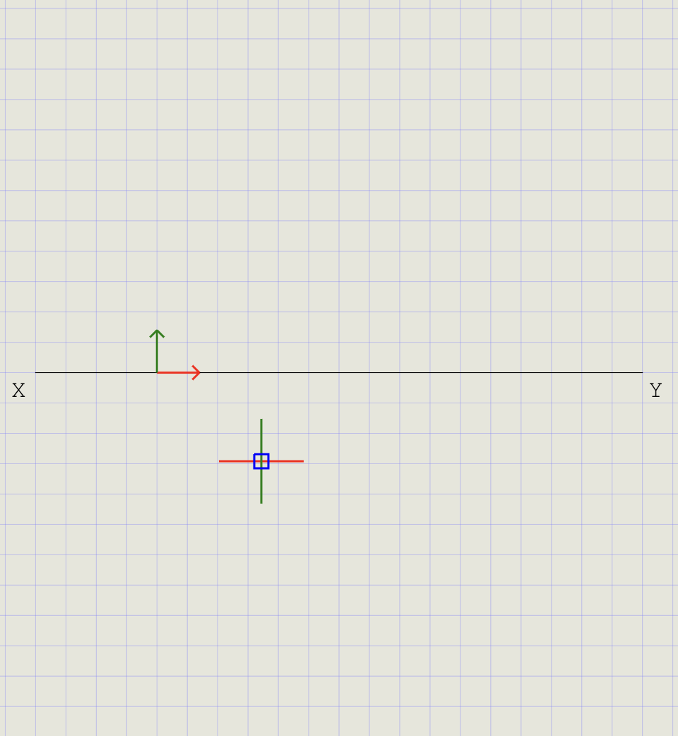
2) Draw the XY Reference Line
- From the Line dropdown, click XY Line
- Pick two points horizontally to draw XY (e.g., ~180 mm)
- Move UCS to one endpoint of XY:
- Click UCS, hover over XY until the Endpoint snap glyph appears, then click
- The UCS origin is now fixed at one end of XY
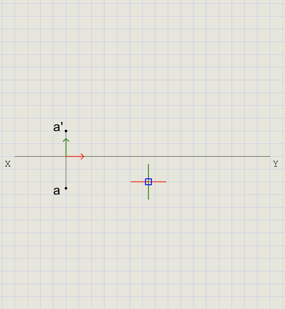
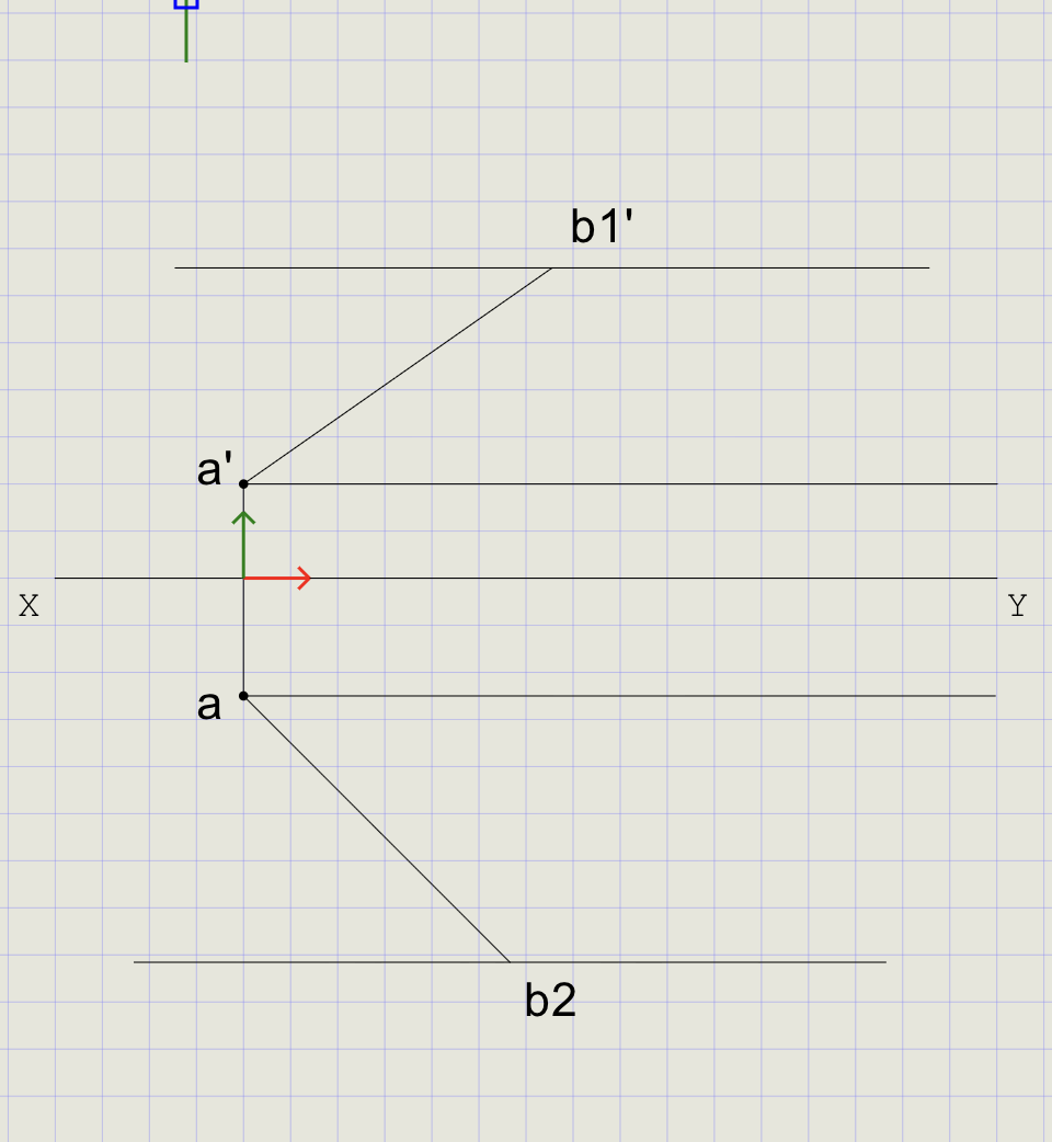
3) Locate Endpoint A in Both Views
Place a (top view) and a' (front view) aligned vertically with the XY reference.
| View | Command | Coordinates | Position |
|---|---|---|---|
| a (Top View) | POINT |
0,-25 |
25 mm below XY |
| a' (Front View) | POINT |
0,20 |
20 mm above XY |
- Draw projector: Run Line, snap to XY, draw a short vertical (Normal thickness)
- Mark a (Top View): Run Point, type
0,-25and press Enter - Mark a' (Front View): Run Point, type
0,20and press Enter - Label Points: Use Text to label the lower point as a and upper as a'
Note
The projector ensures that a and a' are vertically aligned (same generator line).
4) Draw Locus Lines
- Turn Ortho ON from the status bar
- From point a', draw a horizontal line (locus of front view endpoints)
- From point a, draw another horizontal line (locus of top view endpoints)
- Turn Ortho OFF when done
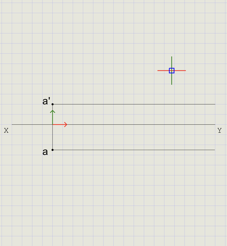
Tip
Locus lines define the horizontal paths along which the other endpoint (b/b') must lie at the same height from XY.
5) First Inclination -- Line Inclined to HP (theta = 35 degrees), Parallel to VP
Construct an auxiliary front view with true length at 35 degrees.
- Click Line on the toolbar
- Click point a' as the start point
- Type
@80<35in the command prompt and press Enter -- draws a line of 80 mm at 35 degrees - Mark the endpoint as b1'
- Line a'b1' is the auxiliary front view (Normal thickness)
- Use Copy to transfer the locus line from a' to pass through b1'
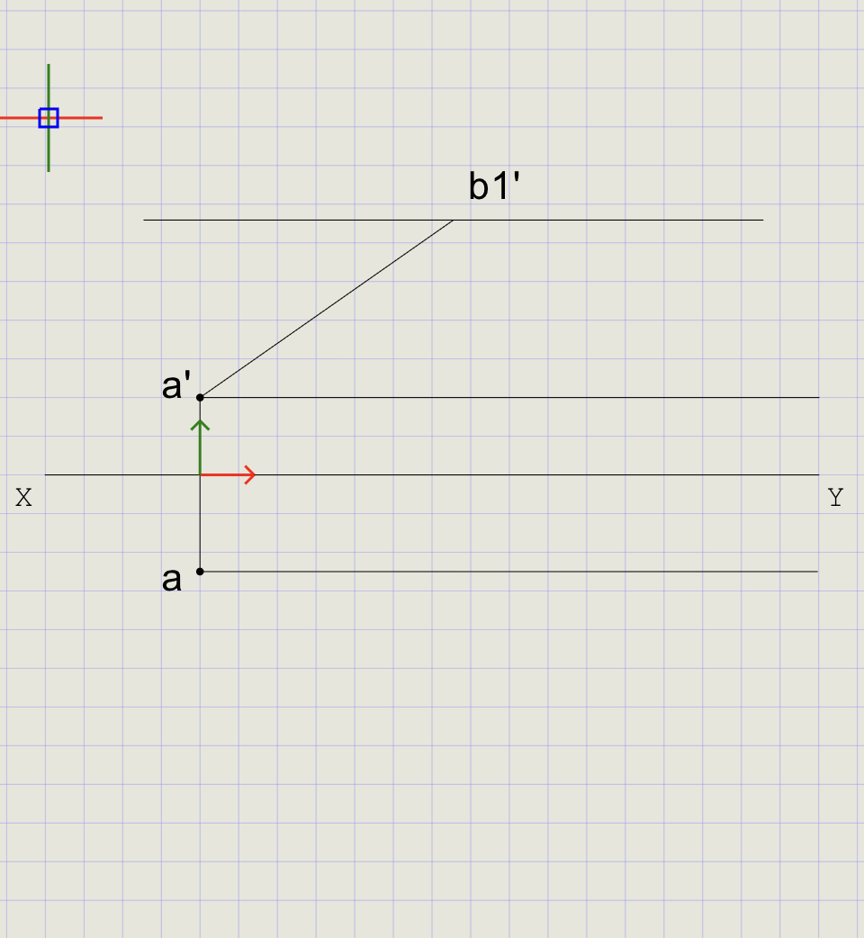
Note
At this stage the line is assumed parallel to VP, so the front view shows the true length at the given angle theta.
6) Second Inclination -- Line Inclined to VP (phi = 45 degrees)
Construct an auxiliary top view at 45 degrees.
- Click Line on the toolbar
- Click point a as the start point
- Type
@80<-45in the command prompt and press Enter -- draws a line of 80 mm at 45 degrees below horizontal - Mark the endpoint as b2
- Line ab2 is the auxiliary top view (Normal thickness)
- Use Copy to transfer the locus line from a to pass through b2
Note
At this stage the line is assumed parallel to HP, so the top view shows the true length at the given angle phi.
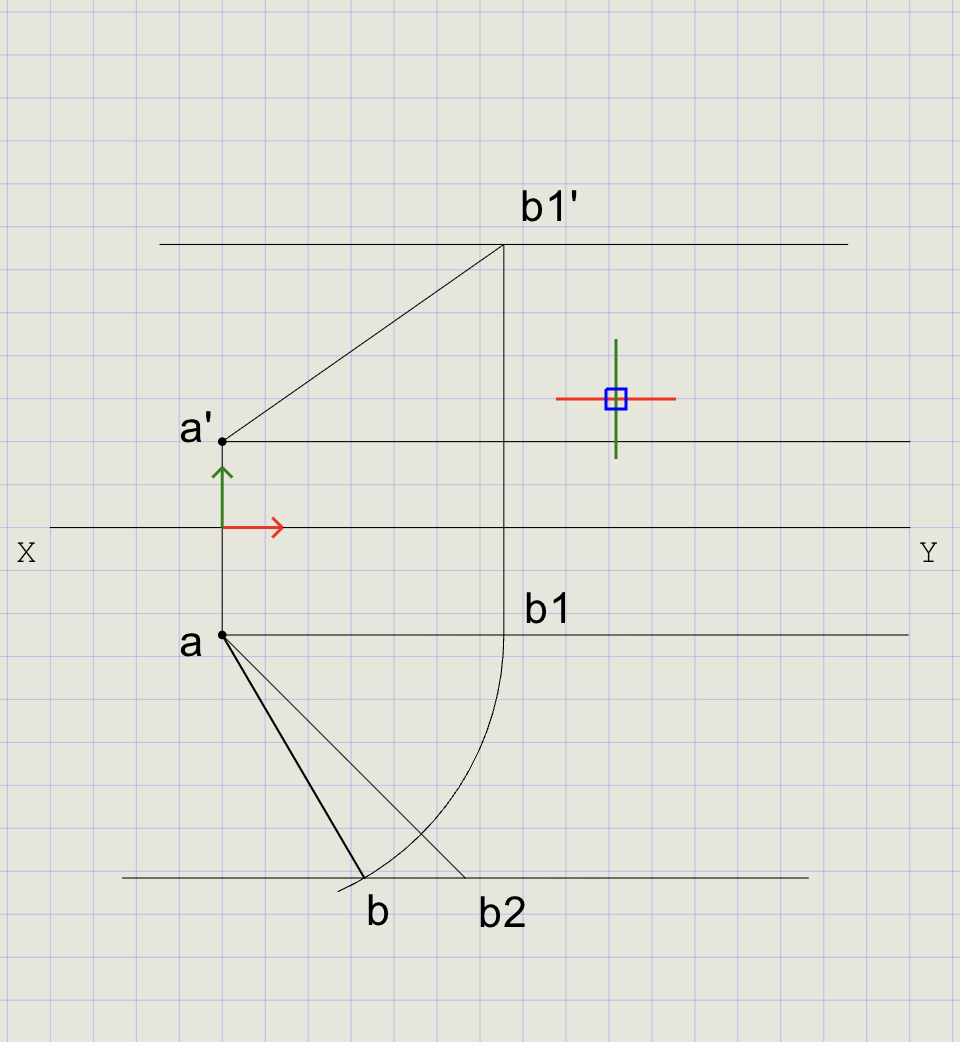
7) Obtain the Final Top View
- From b1', draw a vertical projector down to meet the locus line through a
- Mark this intersection as b1
- From the Arc dropdown, choose Start, Center, End
-
At the prompts:
Prompt Action Start point Select b1 Center point Select a Direction Choose Clockwise End Drag until it meets the locus at b2, then click -
Mark the intersection as b
- Switch thickness to Thick
- Draw the final line from a to b
Tip
The arc radius equals |ab1| (the projected length). Rotating from b1 to the locus of b2 satisfies both inclinations simultaneously.
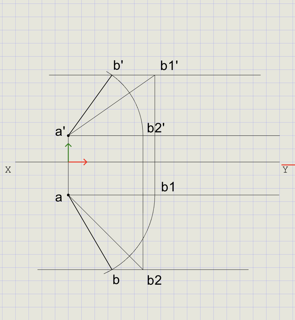
8) Obtain the Final Front View
Repeat the rotation process using the auxiliary top view to locate b' and draw line a'b' in Thick thickness.
- From b2, draw a vertical projector up to meet the locus line through a'
- Mark this intersection as b2'
- Use arc rotation (center = a', radius = |a'b1'|) to locate b'
- Switch to Thick and draw line a'b'
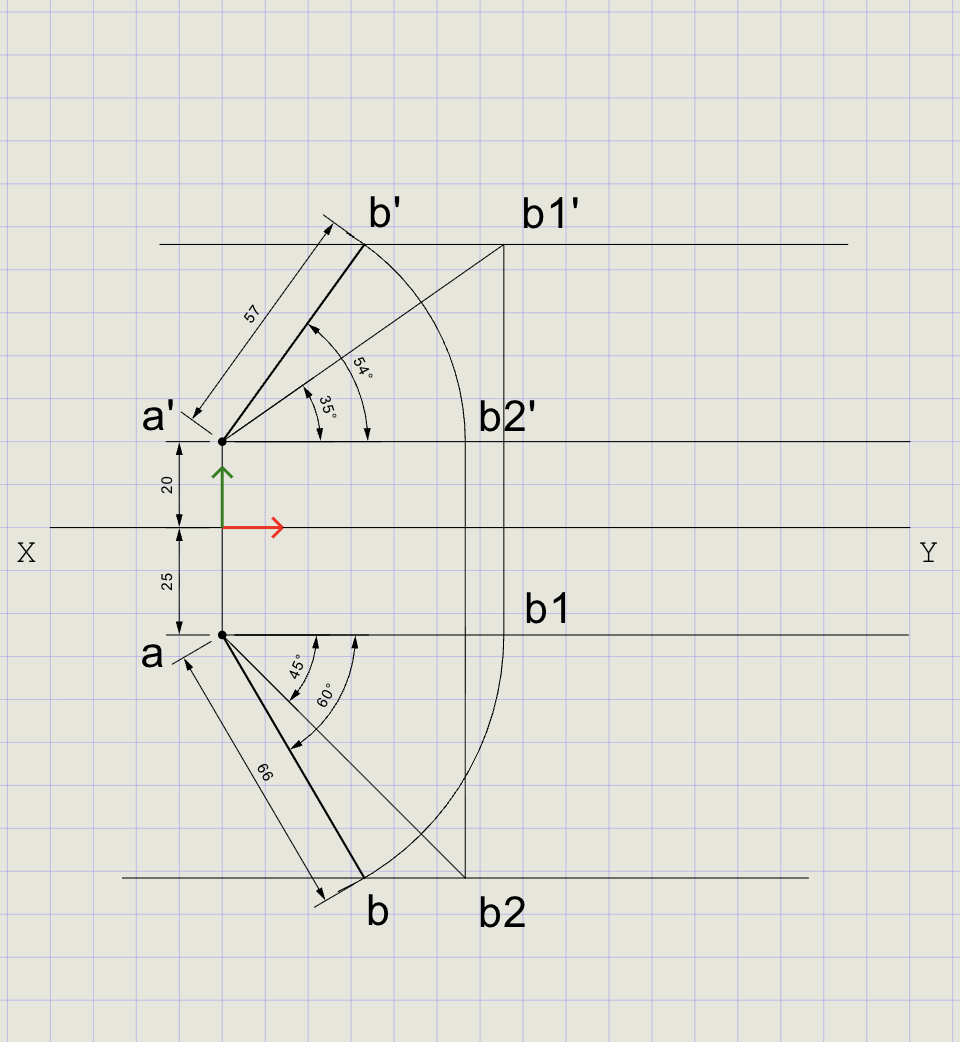
9) Dimensions and Labels
- Switch back to Normal thickness for dimensions
-
Add dimensions:
Dimension From To Value DimLin XY a' 20 mm DimLin XY a 25 mm DimAlign a' b1' 80 mm (true length) -
Label angles theta and phi using Text
Result Checklist
| Item | Status |
|---|---|
| XY drawn with Normal thickness | |
| Entity Snap ON throughout | |
| a placed 25 mm below XY; a' placed 20 mm above XY | |
| Auxiliary front view a'b1' at 35 degrees (Normal) | |
| Auxiliary top view ab2 at 45 degrees (Normal) | |
| Arc rotation used to locate final b and b' | |
| Final views ab and a'b' drawn in Thick | |
| Dimensions: 20 mm, 25 mm from XY; true length 80 mm | |
| Labels: a, a', b, b', theta, phi |
Variations (Practice)
| Variation | What to try |
|---|---|
| Single inclination | theta = 0 degrees, phi = 40 degrees (line parallel to HP, inclined to VP only) |
| Reverse order | First assume phi, then rotate in front view to impose theta |
| Different UCS | Move UCS to different working points for faster typed inputs |
| Different true length | Use 60 mm or 100 mm and observe how views change |
| Both endpoints given | Given distances for both A and B from HP/VP -- verify by construction |
Commands Recap
| Command | Purpose |
|---|---|
xyline |
Draw XY reference line (Normal) |
ucs |
Reposition origin near work area |
point |
Mark a, a', and intermediate b points |
line |
Draw projectors, auxiliary views, and final segments |
arc |
Rotate top/front view about A to match phi/theta while keeping radius = true length |
dimlin |
Linear dimensions from XY to a/a' |
dimalign |
Aligned dimension for true length |
text |
Labels for points, angles, and notes |
| Format | Normal for construction; Thick for final ab and a'b' |
Complete
You've completed the projection of a line using auxiliary views and arc rotation to satisfy both theta and phi, with final views clearly emphasized using Thick line weight. Export to PDF to verify and share.