Projection of a Plane -- VektorCAD Tutorial
This exercise shows how to draw the projections of a plane (lamina) using VektorCAD. You will build the XY reference, construct a true-shape polygon, impose the inclination to HP (theta) and the inclination of an edge to VP (phi), then generate the final top and front views.
What you'll learn
- Constructing a true-shape polygon using the Edge method
- Projecting from top view to front view (edge view on XY)
- Tilting to impose inclination to HP (theta)
- Rotating to impose inclination to VP (phi)
- Obtaining final front and top views by intersection
Problem Statement
Draw the projections of a regular pentagon of side 25 mm, having its surface inclined at 30 degrees to the HP and a side parallel to the HP and inclined at 60 degrees to the VP.
| Given | Value |
|---|---|
| Shape | Regular pentagon |
| Side length | 25 mm |
| Inclination to HP (theta) | 30 degrees |
| Edge inclination to VP (phi) | 60 degrees |
| Condition | One side parallel to HP |
Objective:
| Requirement | Details |
|---|---|
| Commands used | XYLine, UCS, Polygon, Line, Arc, Ray, Point, DimLin, DimAlign, Text |
| Construction lines | Normal thickness |
| Final plane edges | Thick thickness |
| Entity Snap | ON throughout |
Step-by-Step
1) Prepare Drafting Settings
-
Set Line Thickness: Select Normal from thickness options (Thin / Normal / Thick)
-
Entity Snap ON: Turn on snaps -- recommended: Endpoint, Midpoint, Perpendicular for accurate alignment
2) Draw the XY Reference Line
- From the Line dropdown, click XY Line
- Draw a horizontal line approximately 300 mm long
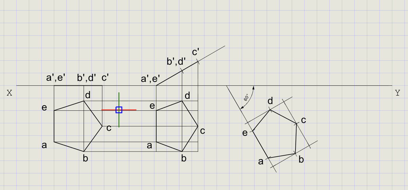
3) Construct the True Shape in Top View (Plane Parallel to HP)
Since the plane is initially assumed parallel to HP, the top view shows the true shape.
- Switch to Thick thickness
- From the Rect/Polygon dropdown, click Polygon
-
At the prompts:
Prompt Action Number of sides Enter 5Method Choose Edge First endpoint Pick a point below XY Second endpoint Enter @25<-90(25 mm edge perpendicular to XY) -
Label the vertices a, b, c, d, e using Text
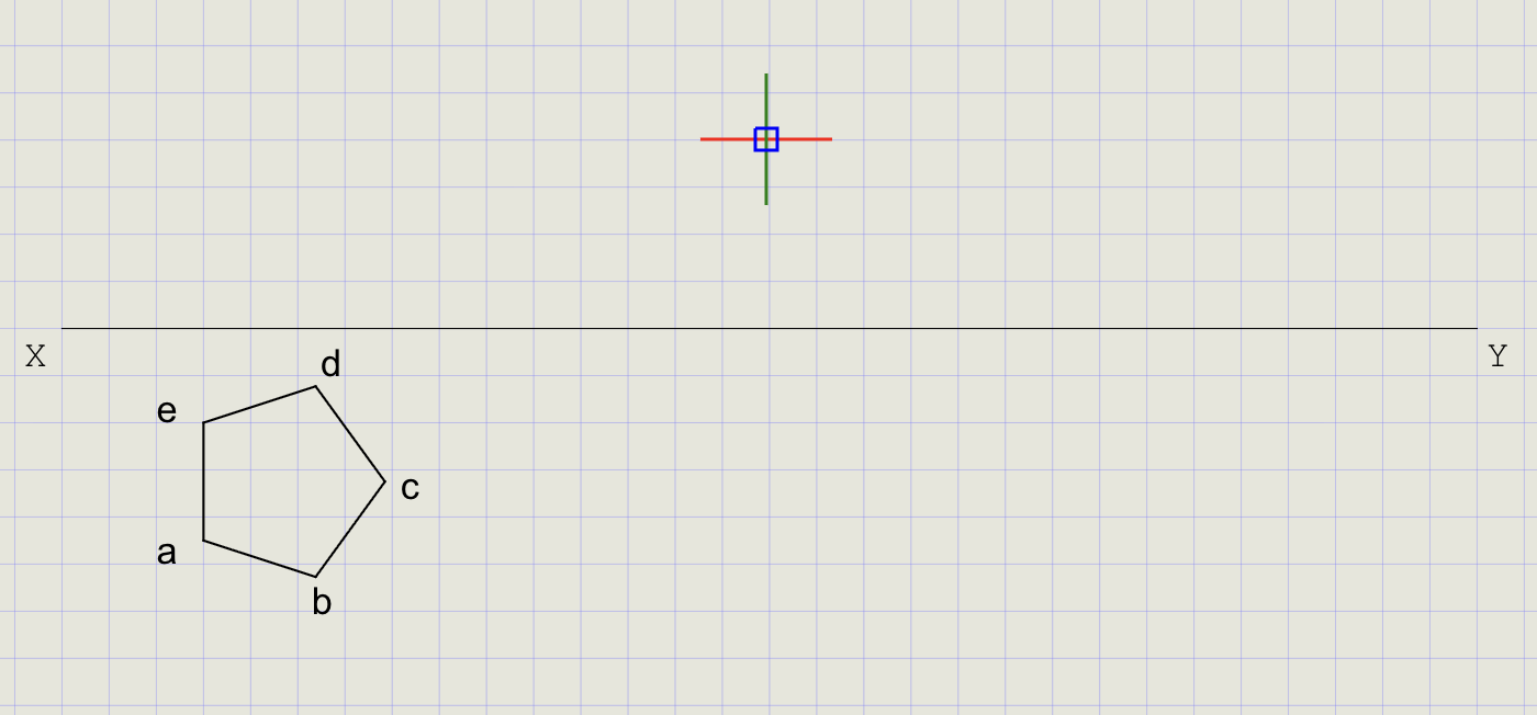
Note
The Edge method lets you control the exact position and orientation of one side. The pentagon is drawn with one edge perpendicular to XY for the initial construction.
4) Project the Initial Front View (Edge View on XY)
Since the plane is parallel to HP, the front view collapses to a line on XY.
- From each vertex (a-e), draw projectors perpendicular to XY upwards using Line (Normal thickness)
- Mark a' and b' on XY where projectors from a and b meet
- Optionally mark c', d', e' on XY for reference
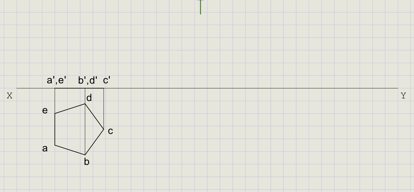
Tip
When a plane is parallel to HP, its front view is always an edge view (a straight line on XY).
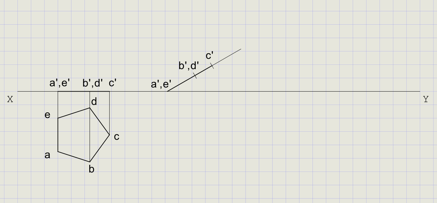
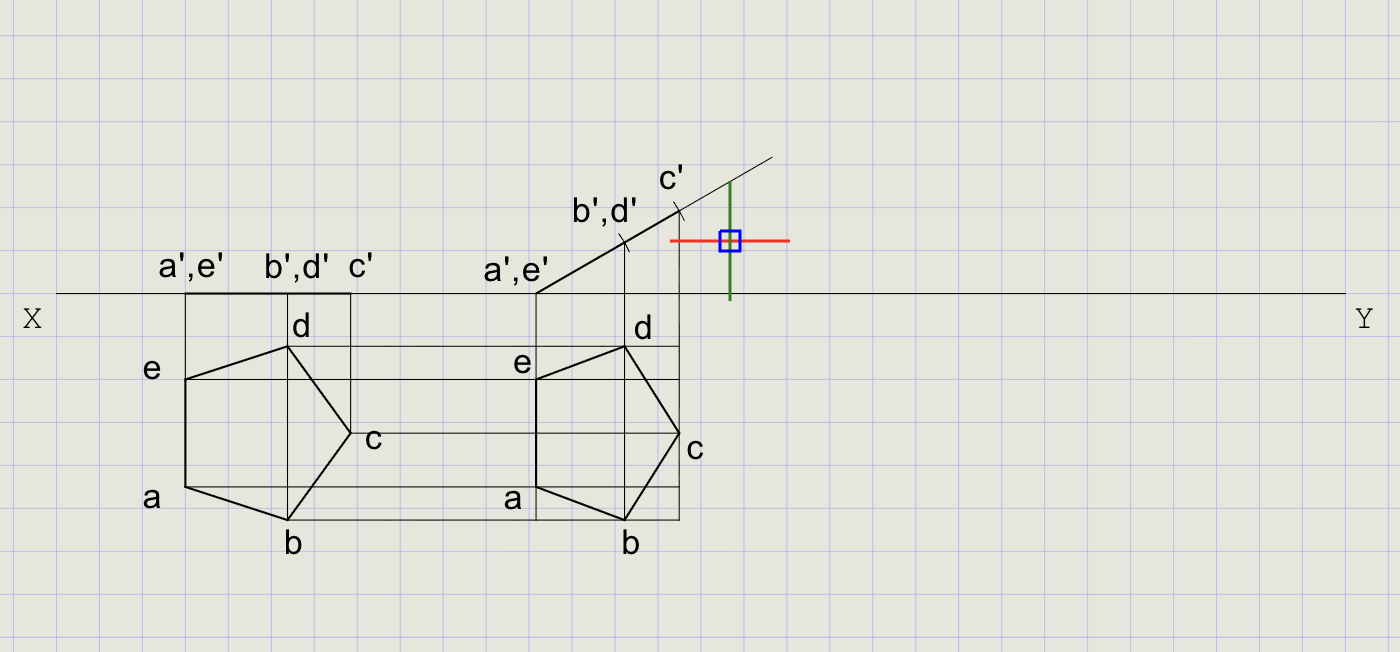
5) Impose theta = 30 degrees to HP (Tilt in Front View)
Rotate the plane about hinge a'b' so the surface is inclined at 30 degrees to XY.
- Click Line on the toolbar
- Right-click, choose Nearest, and snap on XY near c' for the start point
- At the prompt, choose Angle and enter
30 - Pick a point some distance away to finish the line
-
Using Cutting Arc, transfer distances from the top view to the inclined line:
Distance to transfer From To a/e to c' Top view measurement Inclined line a/e to b'/d' Top view measurement Inclined line -
Mark and label the new points along the inclined line
6) Draw Horizontal and Vertical Projection Lines
- From the Line dropdown, click Ray
- Enter
0-- draw horizontals through a, b, c, d, e (top view points) - Run Ray again, enter
90-- draw verticals through a', b', c', d', e' (front view points) - Trim excess rays outside the required intersections
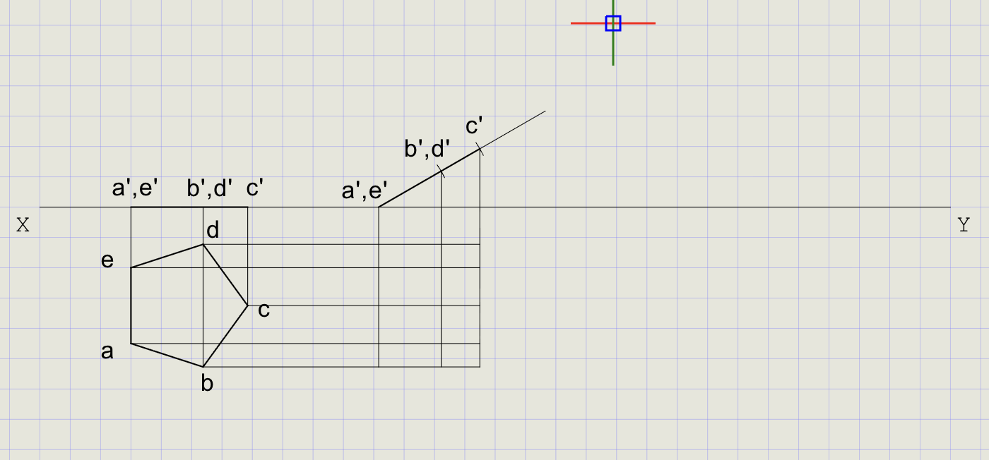
7) Obtain the Top View After Theta
- Mark the intersection points of horizontal and vertical projection lines
- Label them a, b, c, d, e
- Connect with Thick lines to form the tilted pentagon (top view after theta)
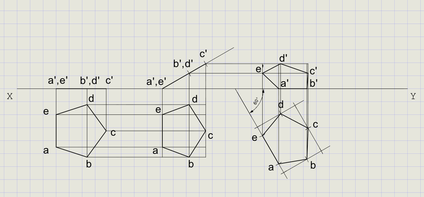
8) Impose phi = 60 degrees to VP (Rotate Top View About AB)
- Click Line on the toolbar
- Right-click, choose Nearest, snap on XY
- At the prompt, choose Angle and enter
-60 - Pick a point below XY to finish the line
- Using Cutting Arc, transfer distances from the tilted top view to the new line
- Mark points a-e and connect with Thick lines
Note
This rotation ensures the specified edge makes the required angle (phi) with VP while maintaining the surface inclination (theta) to HP.
9) Final Front View (After Both Tilts)
- From the new top view points a-e, draw projectors upward (perpendicular to XY)
- From theta-tilted front view points a'-e', draw horizontals
-
Intersections give the final front view positions
-
Redraw final edges in Thick:
View Vertices to connect Top view a-b-c-d-e-a Front view a'-b'-c'-d'-e'-a'
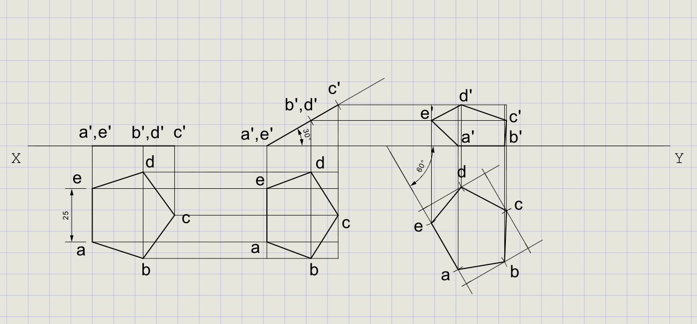
10) Dimensions and Labels
- Switch to Normal thickness for dimensions
-
Add dimensions:
Dimension type What to dimension DimAlign Side length = 25 mm DimLin Vertical offsets from XY Angular Angle of surface with XY (theta, phi) -
Label angles and key points using Text
Result Checklist
| Item | Status |
|---|---|
| XY drawn (Normal) and labeled | |
| Entity Snap ON; UCS positioned conveniently | |
| True-shape pentagon drawn in top view with edge on XY (Thick) | |
| Projectors built; initial front view lies on XY | |
| theta = 30 degrees imposed: front view after tilt obtained | |
| Back-projected top view after theta | |
| phi = 60 degrees imposed: top view rotated about edge | |
| Final front view obtained by projection | |
| Final plane edges in Thick; all construction in Normal | |
| Dimensions (side length, angles) and labels added |
Variations (Practice)
| Variation | What to try |
|---|---|
| Hexagon | Regular hexagon, side 25 mm -- repeat with 6 vertices |
| Equilateral triangle | Side 40 mm -- simpler shape, fewer projectors |
| Swap order | First set phi, then theta -- compare results |
| Perpendicular to VP | Plane perpendicular to VP initially (true shape in front view) |
| Different angles | theta = 45 degrees, phi = 30 degrees |
Commands Recap
| Command | Purpose |
|---|---|
xyline |
Draw XY reference line (Normal) |
ucs |
Reposition origin near work area |
polygon |
True-shape lamina in top view (Edge method, side = 25 mm) |
line |
Projectors, reference lines, and final edges |
ray |
Horizontal and vertical projection rays |
carc |
Transfer distances using cutting arcs (impose theta/phi) |
point |
Mark auxiliary points if needed |
dimlin / dimalign |
Linear and aligned dimensions |
text |
Labels and angle annotations |
| Format | Normal for construction; Thick for final plane edges |
Complete
You've completed the projection of a plane using auxiliary construction and rotation: clean final views in Thick with all supporting geometry in Normal for clarity. Export to PDF to verify and share.